1. This rule is designed for calculating the
dimensions of reinforced concrete beams and slabs and the requirements for reinforcing
steel.
2. This rule is described as "System Jakob". Aristo also made a reinforced
concrete rule which used the system "Götsch".
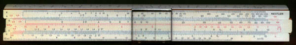
3. The rule has the same body as the Nestler 23R and the slide is also interchangeable.
4. At first the rule looks like a 23R but on closer inspection it has several different
scales some of which are on the edge of the rule and can be accessed using
"flaps" on the sides of the cursor.
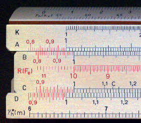
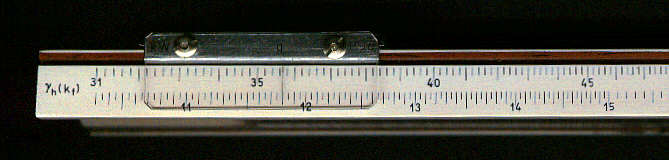
5. The reciprocal scale (normally labelled CI) is labelled Fe. On the top edge
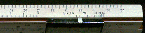
there are two scales the first labelled gh (ks)
and the second gh (kz). At the bottom
edge there is a pair of scales labelled gh (kf)
and on the front face of the rule there is also a scale labelled gh* (m) .
6. The instructions, which for the orginial are very short, are given below.
Summary of instructions
The original instructions are in a very abbreviated form (no explanation of symbols for example) and I have added extra comments in small blue text.
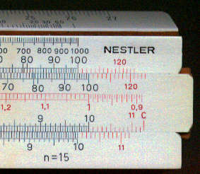
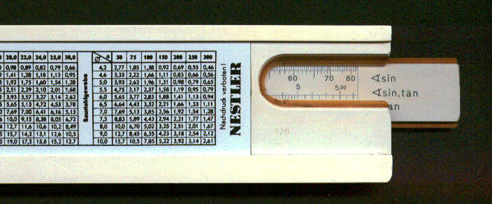
This Nestler rule for reinforced concrete is based on the system Jakob. It is designed for a modulus of elasticity of 15 which is value used in DIN (German Standards Institute 1045). The permitted combinations of units are shown on the table below.
| 1 | 2 | 3 | 4 | |
| M (moment) | kgm | kgcm | tm | tcm |
| b (width) | m | cm | m | cm |
| h (height) | cm | cm | cm | cm |
| se (tension) | kg/cm2 | kg/cm2 | t/cm2 | t/cm2 |
The above table shows the meaning of symbols.
The calculation makes use of the following formulae:
g h = h / Ö (M / b se) ; Fe = b h / kf ;
x = kx h ; z = kz ; m = se / sb
g h* is calculated on the basis of the ratio m = se / sb
(The values of k and g are intermediate values used to facilitate the calculation and do not of themselves have any meaning. )
When g h > g
h* then the arrangement of the reinforcement is straightforward.
When g h < g
h* then the double reinforcement is necessary.
It is not normally necessary to calculate the concrete tension.
The reading of Fe and se is on the Fe (reciprocal) scale.
The reading of all other values is on the D scale.
| g h (kx ) | setting of | g h | for reading of | kx | } | by means of cursor line |
| g h (kz ) | " | kz | ||||
| g h (kf) | " | kf | ||||
| g h* (m) | " | m | (or in reverse) |
Examples of reading scales:
g h (kf) at 8.1 on scale on bottom edge, kf
= 0.543 on D scale.
g h (kz) at 8.1 on scale on right end of top edge, kz
= 0.828 on D scale.
g h (kx) at 8.1 on scale on left end of top edge, kx
= 0.517 on D scale.
g h*(m) at 8.1 on scale on bottom front face, m =
14.0 on D scale.
g h (kf) at 28.0 on scale on bottom edge, kf
= 7.36 on D scale.
g h (kz) at 28.0 on scale on right end of top edge,
kz = 0.938 on D scale.
g h (kx) at 28.0 on scale on left end of top edge, kx
= 0.183 on D scale.
g h*(m) at 28.0 on scale on bottom front face, m =
67.2 on D scale.
A) Slabs
Example 1:
To find: fe, u, se
Given: h=11.5 cm, b=1.0 m, se / sb
= 1400/80 kg/cm2
M1 = 2050 kgm, M2 = 115 kgm, Mb =
1620 kgm
a) First with each function g h* is determined.
For m = permissible se / permissible sb =1400 / 80 = 17.5 gives g
h* = 9.47.
One places C1 to 1400 on D, the cursor to 80 on the Fe scale and reads the answer on the g h* scale (Fig 4).
b) The first step is the calculation of g h
g h = h / Ö (M / b se) = 11.5 Ö (1400) / Ö (2050) = 9.50
For all the values of the moments this gives the following values of g
h:
| Reference | M | g h | Fe |
| 1 | 2050 | 9.50 | 15.05 |
| 2 | 115 | 40.10 | 0.75 |
| B | 1620 | 10.70 | 11.7 |
(It is possible the reference letters 1,2, and B have some special significance.)
c) Place C1 against b x h (= 1.15 in this case) . The values of Fe (steel section?) are then obtained by placing the cursor line against appropriate value of g h (kf) (on the bottom edge of the rule) and reading the values of Fe on the Fe scale (Fig 5.
Since g h* ( = 9.47) is less than g h ( = 9.50) this means that sb is less than 80 kg/cm2 and so no further calculation is necessary (i.e. no additional reinforcement is necessary). For examples if g h was 10.7 and se 1400 kg/cm2 as above then sb = 67.6 kg/cm2 (Fig 7).
Example 2:
To find fe and h
Given M = 925 kgm b = 1.9 m se
/ sb = 2000/70 kg/cm2
a) For m = 200 / 70 = 28.6, g h* = 13.7 (Fig 7).
b) Proceeding in a similar way to example 1.
h = g h Ö (M / se) = 13.7 Ö (925 / 2000) = 9.3 cm.
c) Place the C10 against the value of b x h ( = 9.3). Against the 13.70 on scale gh (kf) read the value of Fe = 5.6 on scale Fe (Fig 8).
Example 3:
To find Fe, and if necessary Fe'
Given: M = 6400 kgm, b = 0.40 m and h = 49 cm se
/ sb = 2200/60 kg/cm2
a) For m = se / sb = 2200/60, g h* = 16.72 (Fig 9).
b) g h = h / Ö (M / b se) = 49 Ö (2200 x 0.40 / 6400) = 18.2 > 19.72 (no need for Fe')
c) Place C1 against b x h ( = 19.6) on scale D and against gh (kf) = 18.2 read the value of Fe = 6.5 on the Fe scale Fig 10).
Example 4:
To find M and Fe
Given h = 43 cm, b = 0.25 m and se / sb = 2000/60 kg/cm2
a) For m = 2000 : 60 g h* = 15.48 (Fig 11)
b) The calculation of the equation g b = h / Ö (M / b se) gives:
M = b se (h / g h)2 = 0.25 x 2000 (43 / 15.48)2 = 3850 kgm
c) Fe = 5.0 cm2 (Fig 12)
Example 4:
To find Fe and Fe'
Given M = 21500 kgm, b = 0.30 m, h = 63 cm, c= 59 cm and se / sb = 2400/80
kg/cm2
a) For m = 2400/ 80 g h* = 14.23 (Fig 13)
b) g h = h / Ö (M / b se) = 63 Ö (2400 x 0.30 / 21500) = 11.52 < 14.23 therefore needs to be doubly reinforced.
For one determines the moment M which the cross section can withstand without compression reinforcement.
M = b se (h / g h)2 = 0.30 x 2400 (63 / 14.23)2 = 14100 kgm
c) Fe1 = 10.5 cm2 (Fig 14).
The the additional reinforcement required for the rest of the moment is calculated.
DM = M - single M = 21500 - 14100 = 7400
Fes = DM/ (c se) = 740000 / (59 x 2400) = 5.23 cm2
Fe = 10.5 + 5.23 = 15.73 cm2
se' = (15 sb + se ) c / h = se = (15 x 80 + 2400) 59 / 63 - 2400 = 970 kg / cm2
Fe' = DM/ (c se') = 74000 / (59 x 970) = 12.9 cm2
or: Fe' = Fes ( h - x) / ( x - h1)
x = kx h = 0.333 x 63 = 21 cm (Fig 15)
Fe' = Fes ( h - x) / ( x - h1) = 5.23 (63 - 21) / (21 - 4) = 12.9 cm2
It is recommended not to use the permissible concrete compressive stress and it generally leads to excessive shear stress which can be handled only with difficulty.
The determination of Fe is carried out in a similar way to a rectangular beam with the
formula:
Fe = M / ( se (h - d/2))
Since the calculation can be carried out as for a normal rectangular cross section by allowing for the additional stress no numerical examples are given.