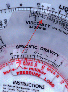
1. This rule is designed for the flow of liquids and gases in
pipes. The front is for pressure loss/flow calculations. The back allows for the
calculation of viscosity, in different systems of units, of various liquids and gases. It
also allows for the determination of whether flow is turbulent or streamline.
2. This rule is quite large - 19.5 cm (7.7 inches) diameter.
3. Although the rule was designed for hydraulics engineers, and must have had help from
them, some of the terms used are slightly unusual. For example the use of the phrase
"rational formula" for pipe flow (it is more normally applied to urban runoff
problems).
4. The front face has a solid outer disc, a thinner rotating inner disc and a rotating
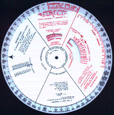
cursor. At the rear there is no cursor.
5. As the rule is large and as I give detailed instructions below, I have not shown
detailed images in the first part of this page.
6. The both discs of the rule are actually a uniform white colour but, maybe because of
different material for the outer disc, in the scanned image the outer disc appears much
darker.
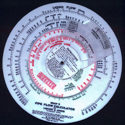
Summary of instructions
Firstly it should be noted that this calculator is
a double-sided instrument, the two sides being entirely independent.
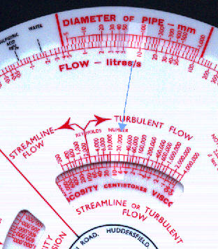
One side determines the flow of water or gases through steel pipes of circular cross
section. The other side deals with three specific problems:
- Determination of viscosity of over 50 liquids.
- Conversion of units of viscosity.
- Determination of whether flow is turbulent or streamlined.
The calculator is designed to solve quickly and accurately the rational formula for the turbulent flow of fluids through pipes, this equation being:-
P = Q2 f S L K / d5
where:—
P = pressure loss, bar.
Q = flow in litre/s for liquids m2/h at 20°C and 1016 mbar for gases.
L = length of pipe, metres.
d = dia. of pipe, mm.
f = coefficient of friction.
S = specific gravity, relative to water for liquids, and relative to air for gases.
K = a constant and is 3.25x l07 for liquids, 3.05 x10³ for gases.
The coefficient of friction varies with viscosity, velocity of fluid and pipe roughness. The velocity variation is built into the calculator and the variation with viscosity is taken care of by the separate viscosity scale.
The values incorporated for the coefficient of friction are as given by the Colebrook-White formula, using an absolute roughness of .045 mm for clean commercial steel or wrought iron pipes as given by Moody, plus an allowance of 2% for pipe joints and a contingency of 3% as it is accepted that the roughness factors for individual pipes cannot be known with complete accuracy.
The value of the constant K in the above formula depends on the definition of the coefficient of friction which Moody gives as half the value given by the Colebrook-White formula as at present used. The formula is:
1 / Öf = - 4 log10 (KS/3.7d + 1.255 / R Öf)
where:-
KS = absolute roughness of pipe in mm
R = Reynolds Number
The formula for the turbulent flow of fluids through pipes given above takes no account of compressibility of gases and the calculator is only applicable so far as gases are concerned to flow around atmospheric pressure, and pressure drops below 0.2 bar. For higher pressures the flow will be larger for the same pressure drop.
On the back of the calculator are tabulated, in alphabetical order, the kinematic viscosities in centistokes at various temperatures and also the specific gravities of over 50 liquids. Scales are also given to convert Redwood No. 1 or Saybolt Universal viscosity to centistokes. If viscosities for other fluids are available in absolute units namely centipoises, then these can be converted to centistokes by dividing by the specific gravity.
It should be born in mind that the viscosities of liquids which are not chemically pure such as fuel oils, crude oil, molasses, etc., are liable to vary appreciably from the average figures given, according to the source of supply and the exact specification. Whilst a variation of say 50% causes little error if the flow is turbulent, it would make a considerable difference if the flow were streamline.
In nearly all practicable problems the flow is turbulent, but scales are provided on the back of the calculator to check on doubtful cases. These scales determine the Reynolds Number and turbulent flow should be assumed at all values above 2,000. The calculator does not solve for streamline flow but the appropriate formula is given on the back for reference.
1. From the back of the calculator confirm that the flow is turbulent and check viscosity and specific gravity. When the diameter or the flow are unknown initially check after these have been determined. If the flow should prove to be streamline as may happen with high viscosity liquids, use the formula given on the back.
2. From the front of the calculator find the flow, pressure loss or pipe size as required.
To find the flow of 98% sulphuric acid at 50°C through an 80mm dia. pipeline 100m long with a pressure loss of 1.0 bar.
On the reverse side set the large black arrow to 98% sulphuric acid. Read off:-
viscosity at 50°C= 5.82 centistokes.
specific gravity = 1.84
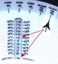
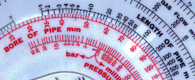
Set 80mm dia to 100 m long.
Set 1.84 specific gravity to 1 bar pressure loss.
Read off:-
FLOW =8.9 litre/s opposite 5.82 viscosity.
Note that the Reynolds number for a viscosity of 5.82 is 25,000 and that consequently the flow is turbulent.
If the pipe has a number of bends or elbows the following additions to the length should be made for each:
| Pipe Diameter (mm) | Length to Add (metres) | ||||
| Welded Elbow | Long Radius Bend | Globe Valve | Gate Valve | Plug valve | |
| 13 | .3 | .15 | 5.5 | .15 | .25 |
| 25 | .6 | .25 | 9 | .25 | .50 |
| 50 | .9 | .5 | 16 | .4 | 1.0 |
| 100 | 2 | .9 | 32 | .75 | 1.5 |
| 200 | 3 | 1.5 | 64 | 1.5 | 3.0 |
| 300 | 4.5 | 2 | 2 | 4.5 | |
| 500 | 7.5 | 3.5 | 3.6 | ||
| 1000 | 15 | 6.5 | 7 | ||
Screwed elbow and bends are double the above figures.
With many fluids the internal roughness will increase due to corrosion and the diameter may be reduced by incrustation, if this is likely an allowance should be made. With pipes handling water for example an allowance of the order of 10% on the volume is desirable.