1. This rule is designed for flow in pipes on one side and for
flow in open channels on the other side.
2. This rule is quite large - 19.5 cm (7.7 inches) diameter.
3. Although the rule was designed for hydraulics engineers, and must have had help from
them, some of the terms used are slightly unusual. For example the use of the phrase
"rational formula" for pipe flow (it is more normally applied to urban runoff
problems).
4. Both faces of the rule have a solid outer disc, a thinner rotating disc and a cursor
with, in effect, multiple gauge points.
5. As the rule is large and as I give detailed instructions below, I have not shown
detailed images in the first part of this page.
6. The both discs of the rule are actually a uniform white colour but, maybe because of
different material for the outer disc, in the scanned image the outer disc appears much
darker.
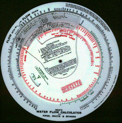
Summary of instructions
Firstly it should be noted that this calculator is
a double-sided instrument, the two sides being entirely independent.
One side determines the flow of water through pipes and ducts of circular cross section
and constructed in a variety of materials, i.e., metal pipes, concrete ducts.
coated pipes etc. The other side deals with the flow in large open channels of any cross
section, rectangular, round, etc.
This side of the calculator solves the rational formula for the flow of fluids in pipes, incorporating coefficients of friction in accordance with the Colebrook-White equation and pipe roughness factors.
The rational formula as applied to water flow is
P = 3.25 x 10⁷ Q2 f L / D5
where:-
P = pressure loss bar
D = bore of pipe, mm.
Q = flow, litre/s
f = coefficient of friction
L = length of pipe, m.
The Colebrook-White equation is :-
1 / Öf = - 4 log (Ks/3.7d + 1.255/RÖf)
where:-
Ks = absolute roughness of pipe in mm. (This approximates to
the dimensions of the particles or granularity of the material causing roughness.)
R = Reynolds Number. (A dimensionless number related to viscosity and
the boundary layer).
The variable coefficient of friction is built into the calculator and needs no separate
determination and a Pipe Material scale makes appropriate allowances for roughness.
The Rational formula combined with the Colebrook-White equation for the coefficient of
friction on which this model is based takes account of pipe roughness, viscosity, and
Reynolds Number and has been practically universally adopted as the most logical and
accurate for problems of fluid flow in pipelines. The answers have been checked against
over 100 well authenticated practical tests on actual pipelines from small metal tubes to
long concrete tunnels up to 6 m dia., and give an accuracy appreciably better than the
usual Hazen-Williams formula. The pressure loss obtained is for pipes in new condition and
allowance should be made for deterioration with age due to corrosion or incrustation
according to experience with the type of water being handled. This will result in an
increased pressure loss or a reduction in the flow.
Scales are provided, coloured green, for determination of velocity.
The flow through any pipe,
duct or open channel running only partly full can be read off directly against the
Proportional Depth scale on the top quadrant. Thus if the depth of water in the pipe is
only one quarter of the diameter, the flow is read off immediately opposite .25 on this
scale.
It will be seen that paradoxically there is a slight increase in the flow with a pipe only
say 95% full, this being due to the appreciable reduction in the length of the wetted
perimeter causing a corresponding reduction in the frictional losses as the water leaves
the top of the pipe.
With partly full pipes the flow is determined by the slope. Thus if the slope is 1 in 600
it will be appreciated that there is a loss of pressure head of 1m in every 600m of
length. To determine the flow therefore the pressure loss is set at 1m and the length at
600m.
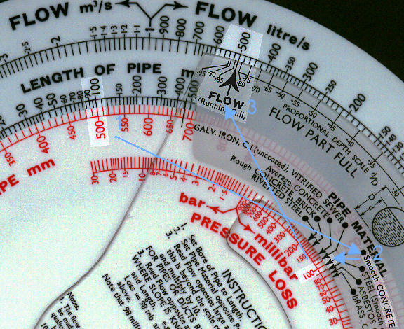 Find
the flow of water through a smooth concrete pipe 500mm bore, l00 m long with a pressure
loss of 100 millibars (1.02 metres head).
Find
the flow of water through a smooth concrete pipe 500mm bore, l00 m long with a pressure
loss of 100 millibars (1.02 metres head).
1. Set 500mm bore to l00 m long.
2. Set "Smooth Concrete" to 100 millibar Pressure Loss.
3. Read opposite outer arrow:
Flow = 507 litre/s
or alternatively if the pipe is only running 30% full read off
against .30 on the Proportional Depth scale:
Flow = 102 litre/s
It is interesting to note that the maximum flow does not occur when the pipe is running full but when it is about 0.95 full. THis is because the sectional area is cloe to maximum but the drag caused by the surface of the pipe is proportionally less.
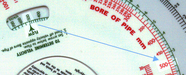 From Velocity Scales: Set green
arrow to 507 litre/s and read opposite 500 mm bore of pipe
From Velocity Scales: Set green
arrow to 507 litre/s and read opposite 500 mm bore of pipe
Velocity = 2.55 in/s
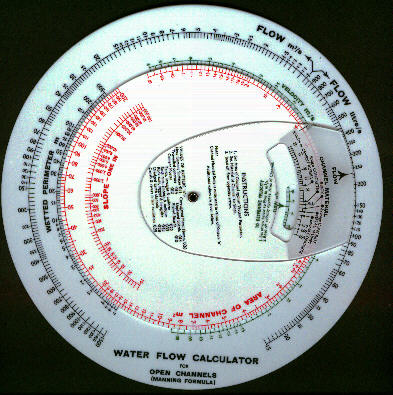
To deal with open channels of
non-circular section the other side of the calculator is arranged to solve the Manning
Formula which is:
Q = A1.66 S0.5 / n P.66
where:
Q = flow in m3/s
A = area of channel in m2
n = Kutters 'n'
P = wetted perimeter of channel in metres.
S = slope of channel
It is necessary to obtain the area of the channel occupied by the water and also the
corresponding length of the wetted perimeter and to use these values in the calculation.
The Manning Formula will also deal with the flow in circular channels running partly full
but it will give low values for the smaller pipes and steeper slopes and it is preferable
to use the other side of the calculator
Find the flow in a 3 in square rough concrete channel with a slope of 1 in 1000 running half full.
Area = 3 x 1.5 = 4.5 m2 .(This is fairly straightforward as if the
channel is half full the weater depth will be 1.5m).
Wetted Perimeter = 1.5 + 3 + 1.5 = 6 m. (The wetted perimeter is the length around the
channel with water touching it. In this case water is touching the whole of the bottom
(3m) and both sides for the depth of water (1.5 at each side).)
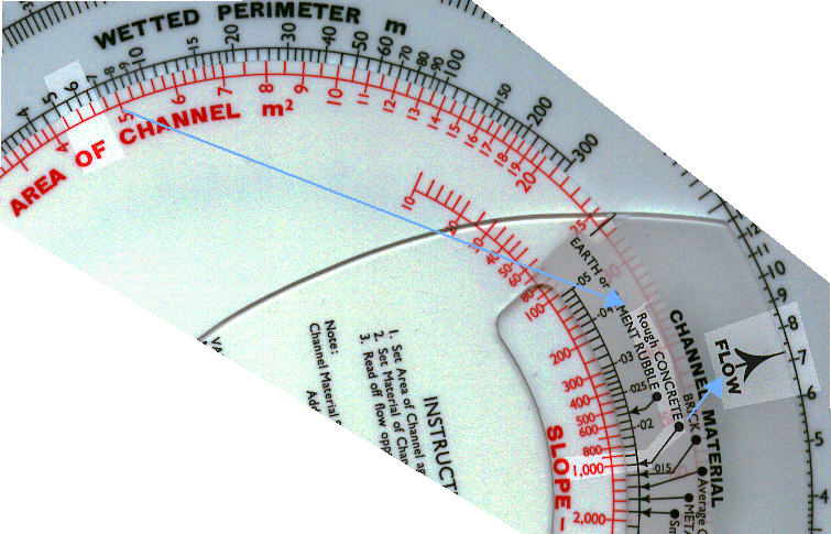
1. Set 4.5m2 Area to 6m Wetted Perimeter.
2. Set "Rough Concrete" arrow to 1000.
3. Read: Flow = 7.36 m3/s
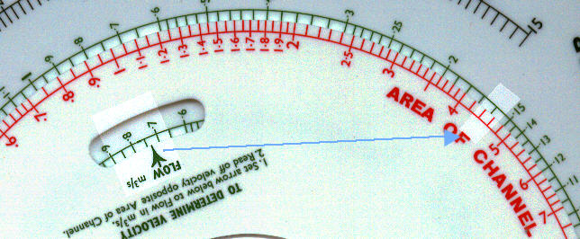
From Velocity Scales: Set green arrow to 7.36 m3/s and read opposite 4.5 m2 area. Velocity = 1.64 m/s
If the pipe has a number of bends or elbows the following additions to the length should be made for each:
| Pipe Diameter (mm) | Length to Add (metres) | |||
| Welded Elbow | Long Radius Bend | Globe Valve | Gate Valve | |
| 13 | .3 | .15 | 5.5 | .15 |
| 25 | .6 | .25 | 9 | .25 |
| 50 | .9 | .5 | 16 | .4 |
| 100 | 2 | .9 | 32 | .75 |
| 200 | 3 | 1.5 | 64 | 1.5 |
| 300 | 4.5 | 2 | 2 | |
| 500 | 7.5 | 3.5 | 3.6 | |
| 1000 | 15 | 6.5 | 7 | |
Screwed elbow and bends are double the above figures.
The volume flow of water at 65°C in steel pipes is approximately 3% greater than at 10°C for the same pressure loss.