1. This rule is designed for calculating the dimensions of
reinforced concrete beams and slabs and the requirements for reinforcing steel.
2. This rule is described as "System Götsch". Nestler also made a reinforced
concrete rule which used the system "Jakob".
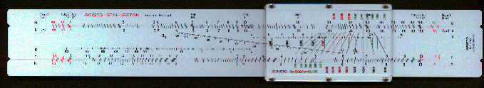
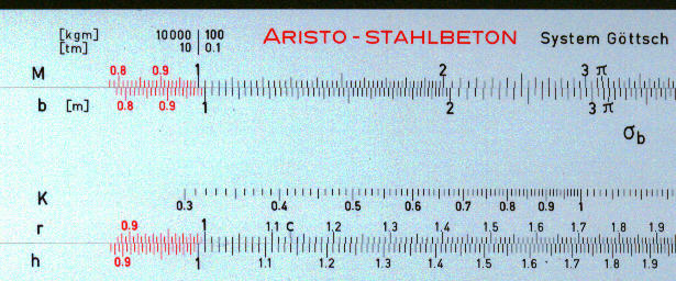
3. The main scales on the front of the rule are, in effect, the normal A and D on the
stock and B and C in the slide. These scales are marked M, for bending moment, b, for
breadth of cross-section, r, values for the verification engineer and h, for height. There
is also special scale labelled K, intermediate values for calculating area of reinforcing
steel.
4. The rule also has a very special cursor with multiple lines, many of them curved. The
use of the cursor is explained below.
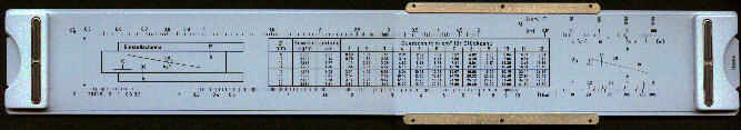
5. The back of the rule has a number of scales for calculating other dimensions and also a
table of weights and sectional areas of standard sizes of steel reinforcing bars.
Summary of instructions
One of the basic concepts in structural engineering is the "bending moment". It has the dimensions of length times force. In the simple case of a beam supported at both ends carrying a uniform load the maximum bending moment is at the centre of the beam. In this case the bottom of the beam is in tension but the top of the beam is in compression. Concrete is very good at resisting compression but poor at resisting tension. By placing steel bars in those parts of the concrete under tension best use is made of the different properties of these two materials.
Another concept is "shear stress". This is proportional to the rate of change of bending moment and is at its maximum at the end of the beam.
The rule is not specifically designed for calculating the bending moments or shear stress but for calculating suitable dimensions and reinforcement needed.
Whilst a beam, as described above, is a simple case, most structures are more complicated involving a combination of beams, columns and slabs, few of which will be simply supported at the ends.
Most countries had their own "codes of practice" which laid down rules relating to methods to be applied and assumptions which could be made when designing reinforced concrete structures. The normal cursor provided with this rule, which had the reference L939/15, was intended for use with the German code (DIN 1045). This covered a range of tension in the steel from 1200 to 2800 kg/cm2. The cursor on the rule shown here (which was used by a French structural engineer but which had the instructions in Spanish) has the reference L939/10 and covered the range 880 to 2200 kg/cm2. A third option had the reference L939/8 and covered the range 880 to 2000 kg/cm2.
The rule could be used for rectangular beams, with single or double reinforcement, slabs and T-beams. It could be used for bending along an axis, longitudinal forces and shear.
 This
diagram shows a cross section through a beam. Typically, part of the cross-section will be
in compression, the upper part on the middle of beam for example, and part in tension. For
any given bending moment there is a large number of options for dimensions of the beam and
for reinforcement. The normal procedure is to try different combinations of height and
breadth for given loads and strengths of materials and select the one which is most
economical.
This
diagram shows a cross section through a beam. Typically, part of the cross-section will be
in compression, the upper part on the middle of beam for example, and part in tension. For
any given bending moment there is a large number of options for dimensions of the beam and
for reinforcement. The normal procedure is to try different combinations of height and
breadth for given loads and strengths of materials and select the one which is most
economical.
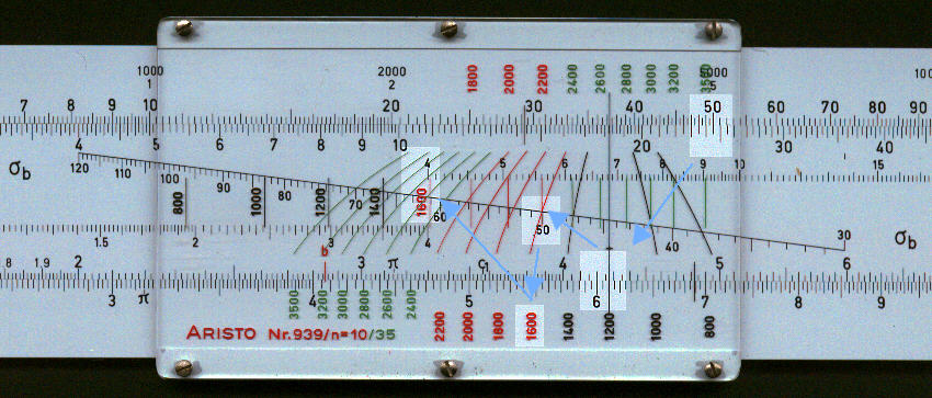
The example below shows the following values:
- The breadth (25 cm) on the slide is set against the bending moment (5200 kg.m) on the upper stock.
- The vertical line on the cursor is then aligned with the height (61 cm).
- The curved lines on the cursor relate to the tension in steel (se = 1600 ) kg/cm2 given by the numbers at the bottom of the cursor (3500 to 2400 2200 to 1600, and 1400 to 800).
- These curved lines pass through the compression in the concrete (sb = 50 kg/cm2 ) on the sloping line of the slide.
- The numbers in the centre (800 to 1400 and 1600) and top (1800 to 2200 and 2400 to 3500) of the cursor have the same meaning as the numbers at the bottom but align with the K scale, K being an intermediate value without specific significance. In this case the value of 1600 kg/cm2 aligns with a K value of 4.02.
- The value of r, 0.427 on scale on lower edge of the slide, is used for cross-checking
calculations.
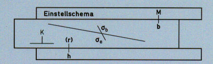
A small diagram on the back of the slide gives a summary of the relative position of the different variables.
With this cursor the sectional area of steel is given by:
Fe = 1.5 * h (cm) * b (m) / K
In our case Fe = 1.5 * 61 * .25 / 4.02 = 5.7 cm2.
With the number 15 cursor the factor of 1.5 in the above equation become 1.0 and with
the number 8 cursor the factor becomes 1.875.
A table on the back of the slide gives the sectional area of different numbers of
reinforcing bars of different standard diameters.
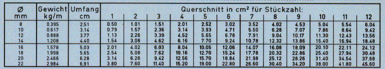
From this table we can see that two bars of 20 mm diameter would give enough steel and also that a 20 mm bar would weight 2.477 kg/cm.
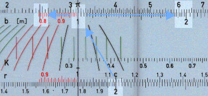
The same calculation can be performed on the front of the rule using extra hairlines on the cursor. Setting the small hair line at the bottom right against the diameter (20mm) gives the sectional area (3.14 cm2) against the principal hairline on the stock. One can multiply this area by the number of bars to give the total sectional area, in this case 6.28 cm2. From the area of the bar (3.14 cm2) we can use the second small hair line to get the weight per metre, 2.47 kg.
It would be unusual to have just two fairly thick bars in a beam of 25 cm width; the above number was chosen for convenience of presentation.
The distance x, (see above diagram) is the depth of the zone of compression.
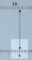 The
back of the rule has a special scale for this. There is a scale marked x on the stock and
special marks on the slide, with the black dot with a line through it. This line is
brought against the value K, in our case 4.02, previously found.
The
back of the rule has a special scale for this. There is a scale marked x on the stock and
special marks on the slide, with the black dot with a line through it. This line is
brought against the value K, in our case 4.02, previously found.
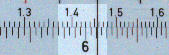 On the front of the rule against the height, in our case 65 cm, is the
value of x, 14.58 cm.
On the front of the rule against the height, in our case 65 cm, is the
value of x, 14.58 cm.
There are other scales by which other special dimensions can be obtained in a similar way.