Air navigation computers form an important sub-class of slide rules. They are also one of the few types still sold commercially. And it's easy to see why - if you are worried that the head-wind seems stronger than forecast and are uncertain about whether to divert to an alternative airport or not that last thing you want is a flat battery on your electronic calculator!.
The rules can be used for four different types of calculations:
- As a normal slide rule, for example for speed/time/distance calculations.
- Using in-built tables, for example temperature conversion.
- Using special scales, for example altitude temperature correction.
- Wind triangle calculations, for example heading and drift.
We give a brief description of each of these types of calculations below.
Use as a slide rule
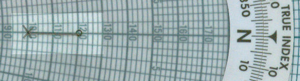
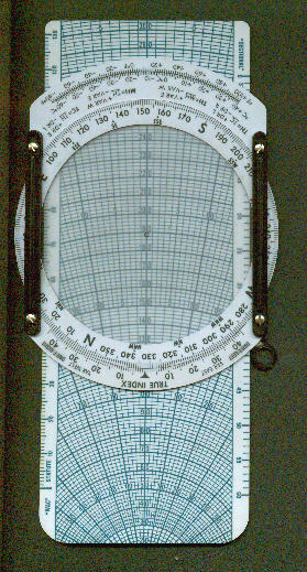
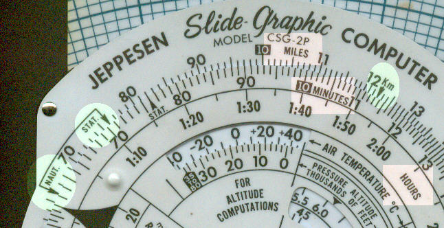
1. Two differences which stand out between an aviation and a normal circular slide rule (small images above and Figure 1) are:
- There is no cursor
- The lettering and scale markings are much heavier.
These reflect the special purpose of the rule; when you are flying the aircraft with one hand and operating the rule with the other and simultaneously keeping an eye on the instruments, looking out for other aircraft and reading the scales, you want to be sure what you are doing.
2. The two scales (equivalent of the C and D scales) are labelled miles and minutes (highlighted in pink). This is because one of the most common types of calculation performed with this part of the rule is time/speed/distance. The both represent a single cycle logarithmic scale. Note however that the inner scale is duplicated with a minutes and hours scale - this again is to facilitate calculation for short and long flight times.
3. The rule also has the equivalent of gauge points. The ones highlighted in green are for conversion between nautical miles, statute miles and kilometres.
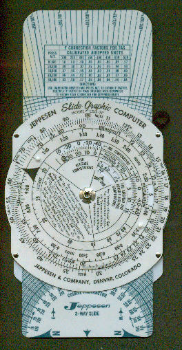
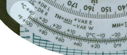
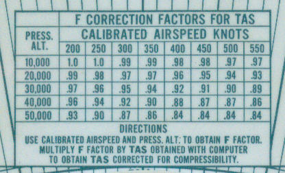
We give below two examples of "tables". The first shows two scales for temperature conversion (Figure 2) . The second shows correction factors for TAS (True Air Speed) relative to pressure altitude (Figure 3). The two terms in italics both have special meaning. Air speed is measured by comparing the difference in pressure between a small tube pointing forwards and air pressure. This measure is not accurate and compensations have to be applied to get the true air speed. The pressure altitude is the altitude read when the altimeter is set to standard sea level pressure. The pressure altitude has the advantage that all aircraft can maintain vertical separation; the disadvantage is that mountains do not understand pressure altitude.
Take off performance of an aircraft is effected by pressure and temperature. Very roughly, take off distance is increased by 1% for 1°C increase in temperature and by 10% for each 1000 ft increase in altitude. (Notice to aviators - do not rely on these figures or if you are stupid enough to do so - don't sue me!).
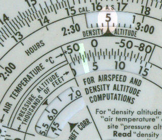
The pressure altitude makes a number of assumptions about the atmosphere which may not be valid. Runways are bit like mountains and do not understand pressure altitude, what they understand is density altitude. The scales to the right show that for a pressure altitude of 3000 ft and a temperature of 25°C (highlighted in green) the density altitude is 5000 ft (highlighted in pink).
1. The first diagram below (figure 6) show a typical wind vector. If an aircraft is heading east at 120 knots and there is a wind of 20 knots from the north then the actual track of the aircraft will be 90° plus tan-1(20/120), that is 99.5°. The ground speed will be 120 / cos(tan-1(20/120)), that is 121.7 knots. Not too difficult with a slide rule while sitting at your desk but ...!
2. To perform the same calculation with the Jeppeson, you first draw the wind vector by setting the compass to the wind direction (0°) and drawing a line the scale length of the wind velocity (figure 7).
3. You then turn the compass to your heading, 90° (i.e. east). You can then read off your drift, 9.5°, using the drift scale (highlighted in green) and your ground speed, 121.5 kts, using the circular speed scales.
4. There are of course many other calculations which can be performed using the wind vector, the common one being to determine what heading you have to fly at knowing the forecast wind speed and direction and bearing between your departure airport and your destination. Another common use is to re-calculate the wind speed whilst in the air based on your heading and observed drift.